Hello Robonesians, in the world of digital electronic system design or integrated circuit design (IC design), Hardware Description Language or abbreviated as HDL is the most important programming language used to create designs and models of programmable digital hardware such as FPGA (Field Programmable Gate Array) and ASIC (Application-Specific Integrated Circuit). HDL allows engineers, electronics engineering students, and embedded systems developers to create, verify, and test hardware designs without having to create a physical circuit first. In other words, HDL is a language for writing hardware just like we write software.
1. What is HDL?
Hardware Description Language (HDL) is a programming language used to describe the structure, behavior, and architecture of digital systems. Unlike programming languages like C or Python, which execute instructions sequentially (serially), HDL works in parallel, following the principles of concurrency, just like real digital circuits.
HDL programming languages can be used for:
- Creating digital logic circuit designs (combinational and sequential).
- Simulate the behavior of digital systems before implementation.
- Performing synthesis into a physical circuit on an FPGA or ASIC chip.
- Automatically perform hardware design verification and validation.
2. Types of HDL
There are four main HDLs widely used in the semiconductor industry and academic research: VHDL, Verilog, SystemVerilog, and SystemC. Here’s a brief explanation of each, along with its excess and lack:
2.1 VHDL (VHSIC Hardware Description Language)
- Developed by the United States Department of Defense on the VHSIC (Very High-Speed Integrated Circuit) project.
- It has a strict and very formal syntax.
- Suitable for complex and structured designs.
- Widely used in academic world and large scale projects.
- Popular tools: Xilinx Vivado, Intel Quartus, ModelSim.
Excess:
- Strongly typed data types.
- Documentative and easy to maintain.
- Supports behavioral and structural modeling.
Lack:
- The syntax is longer and more complicated than Verilog.
2.2 Verilog HDL
- Developed by Gateway Design Automation in the late 1980s.
- The syntax is similar to C language, so it is easy to understand for users who have mastered programming languages such as C, C++, Python, or others.
- Very popular for FPGA and ASIC designs.
Excess:
- Easy to learn and efficient for rapid prototyping.
- Wide support by various FPGA vendors.
Lack:
- Data types are less strict than VHDL.
2.3 SystemVerilog
Development of Verilog with modern features such as:
- Object-Oriented Programming (OOP)
- Assertions
- Interfaces
- Randomization for complex design verification
- Widely used in the SoC (System-on-Chip) industry for design and verification.
Excess:
- Combination of design and verification capabilities.
- Supports coverage-driven verification.
Lack:
- More complex and requires a complete toolchain.
2.4 SystemC
- Based on the C++ language, developed by the Open SystemC Initiative (OSCI).
- Intended for high-level system modeling (System-Level Design), including hardware and software.
- Generally used for co-simulation between hardware and software.
Excess:
- Integrated with C++ programming language, easy for software engineers.
- Suitable for high-level modeling, rapid simulation, and complex system architecture design.
Lack:
- Not all SystemC code can be synthesized directly to an FPGA/ASIC.
- Requires a deep understanding of the C++ programming language and system simulation
3. Simple Example of HDL Program
The following is an example of implementing an AND logic gate (AND Gate) using four different HDL languages.
3.1 VHDL
|
1 2 3 4 5 6 7 8 9 10 11 12 13 |
library IEEE; use IEEE.STD_LOGIC_1164.ALL; entity AND_Gate is Port ( A : in STD_LOGIC; B : in STD_LOGIC; Y : out STD_LOGIC); end AND_Gate; architecture Behavioral of AND_Gate is begin Y <= A and B; end Behavioral; |
Explanation:
entity defines ports (input/output), while architecture describes logical behavior.
3.2 Verilog
|
1 2 3 4 5 6 7 8 |
module AND_Gate ( input wire A, input wire B, output wire Y ); assign Y = A & B; endmodule |
Explanation:
A module is the main block of a design. Assign is used to describe the logical relationship between inputs and outputs.
3.3 SystemVerilog
|
1 2 3 4 5 6 7 8 9 10 |
module AND_Gate ( input logic A, input logic B, output logic Y ); always_comb begin Y = A & B; end endmodule |
Explanation:
always_comb is a special block in SystemVerilog for combinational logic. The logic type replaces wire for greater flexibility.
3.4 SystemC
|
1 2 3 4 5 6 7 8 9 10 11 12 13 14 15 |
#include <systemc.h> SC_MODULE(AND_Gate) { sc_in<bool> A, B; sc_out<bool> Y; void process() { Y.write(A.read() & B.read()); } SC_CTOR(AND_Gate) { SC_METHOD(process); sensitive << A << B; } }; |
Explanation:
SystemC uses C++ classes and methods. SC_METHOD defines a function that is executed whenever the input signal changes.
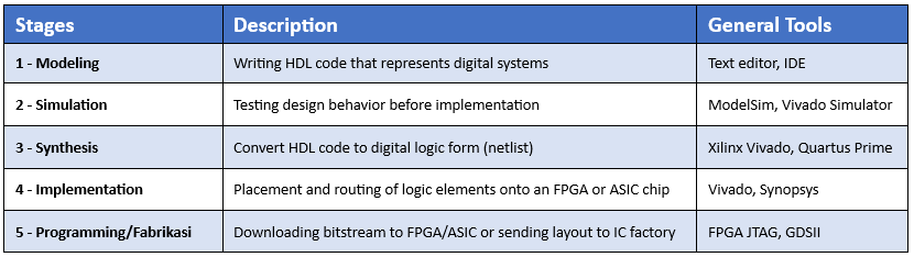
4. Hardware Design Process with HDL
General stages in HDL-based digital design include:
Table 1. HDL-based digital design
5. Application of HDL
HDL is widely used in various fields of modern technology, including:
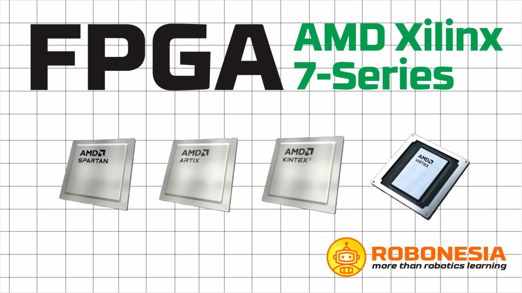
- FPGA Design: flexible digital system design for industrial control, robotics, and data communications.
- ASIC Design: manufacturing custom chips for processors, GPUs, sensors, or IoT devices.
- Embedded System: integration of HDL with microprocessor software.
- Signal Processing: digital filters, encoders, and communication modules.
- SoC Verification: using SystemVerilog or SystemC for design validation.
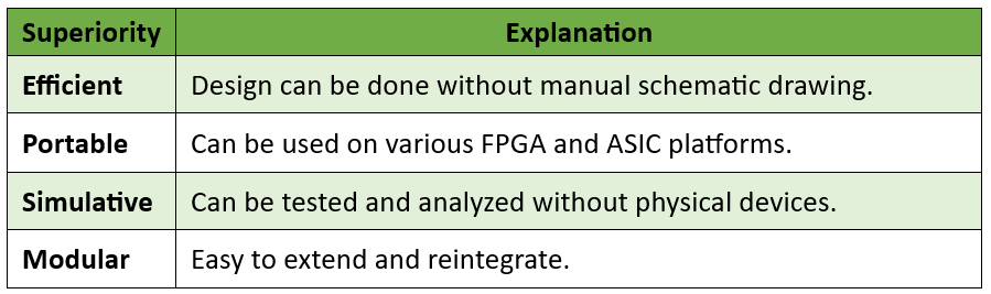
6. Advantages of Using HDL
The advantages of using HDL are listed on the table 2 below.
Table 2. The advantages of using HDL
7. Challenges and Tips for Learning HDL
Learning HDL requires an understanding of the concepts of hardware concurrency, timing, and clock synchronization. Here are some tips for beginners:
- Start with simple projects like logic gates and counters.
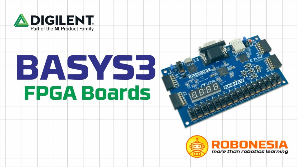
- Use a board like Basys3 (Artix-7) or DE10-Lite (Cyclone V).
- Learn synthesis vs simulation.
- Master electronics design automation (EDA) such as Vivado, Quartus, and ModelSim.
- Document every experiment for a professional portfolio.
8. Conclusion
HDL is the foundation of modern digital electronics hardware design. By mastering HDL programming languages such as Verilog, VHDL, SystemVerilog, and SystemC, engineers can create complex digital electronics systems, from FPGA prototyping to ASIC production. HDL is not just a programming language, but a tool for building the digital world (digitization). Mastering it opens the door to a professional career in IC design and embedded systems.