Hello Robonesians, this article will explain numbers in Verilog programming. The discussion will cover the definition of numbers, number types, base/radix, bit size/width, and recommended and non-recommended number representation formats in Verilog programming.
6.1 Numbers in Verilog Programming
Numbers in Verilog programming are a fundamental concept used to represent numeric values in digital system design. Numbers need to be defined in the hardware description of a digital system design, namely as the logic state of signal lines, buses, delay values, and numbers to be loaded into a register.
6.2 Number Types in Verilog Programming
Verilog programming recognizes two types of numbers, namely:
- Integer (int): is a whole number that has no decimal part.
- Example: 1, 7, 10, -17.
- Real: is a number that has a decimal part (numbers after the decimal point).
- Example: 3.17, -0.7, 2.75.
6.3 Base (Radix) of Numbers in Verilog Programming
Verilog uses several number bases (also called “Radix”) to represent numeric values in digital system design, including:
- Base 2 Numbers – Binary: Binary numbers are numbers written in a base 2 system and are written in a digital system starting with the letter ‘b’ or ‘B’. Binary numbers consist of two digits, namely 1 and 0.
- Example: b1010, B1101
- Base 8 Numbers – Octal: Octal numbers are numbers written in the base 8 system and are written in the digital system starting with the letter ‘o’ or ‘O’. Octal numbers consist of 8 digits, namely 0, 1, 2, 3, 4, 5, 6, and 7.
- Example: o10, O25, o377
- Base 10 Numbers – Decimal: Decimal numbers are numbers written in a base 10 system and do not begin with a specific letter character, as in binary, octal, or hexadecimal. Decimal numbers consist of 10 digits: 0, 1, 2, 3, 4, 5, 6, 7, 8, and 9.
- Example: 8, 28, 128
- Base 16 Numbers – Hexadecimal: Hexadecimal numbers are base 16 numbers which in digital writing begin with the letter ‘h’ or ‘H’. Hexadecimal numbers consist of 16 digits, namely 0, 1, 2, 3, 4, 5, 6, 7, 8, 9, A, B, C, D, E, and F.
- Example: h10, H25, hFF
6.4 Bit Size/Width of Numbers in Verilog Programming
In digital system hardware modeling, it is sometimes necessary to represent numbers with different bit widths (sizes). This raises the question, “Why is it important in digital system design to consider the bit width used to store the value and size of a number?”
The answer is:
Because an IC design engineer must always remember that the hardware area (semiconductor wafer) for the digital system design he builds is limited, so the digital system design must be efficient in size (size) and have the principle that the smaller the size of the digital system design, the more the number of ICs produced in one semiconductor wafer. So, considering the use of size or bit-width numbers in digital system design is a very important thing to consider.
In the simulation process, the bit-number or bit-width or size of the number is important for some operations. But for the synthesis process of digital system design, the size of the number (Size) becomes more important. It is a waste of hardware area usage if a digital system design actually only requires 8-bit hardware area, but the synthesis results use 32-bit hardware area, because the width of the number is not specified by the IC design engineer. Therefore, it is a good habit for IC design engineers to always inform the Verilog compiler regarding the size or bit width of a number required for the digital system design they are building.
6.5 Recommended Number Representation Formats
In Verilog programming, numbers can be specified in binary (base 2), octal (base 8), decimal (base 10), or hexadecimal (base 16) form. The recommended number representation in Verilog programming has three main elements, namely size, radix/base, and value. If there is a need for a particular digital system design, this number representation can be added with a negative sign (“-“) in front of the size element to make the number a signed number, but this is only optional. Figure 1 shows the recommended number representation format in Verilog programming with each component explained separately.
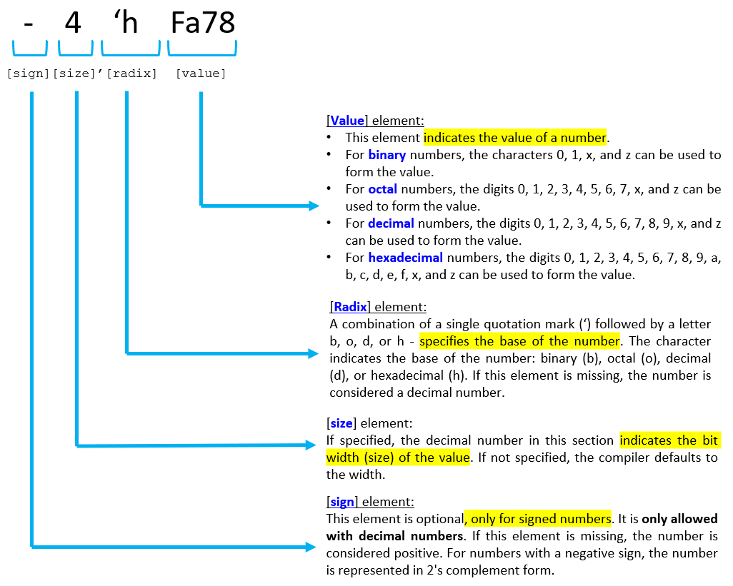
Figure 1. Number representation format in Verilog programming
The following is an explanation for each element in the number representation format in Figure 1:
1. The [Sign] Element
- The “Sign” element is a minus sign (“ – “) placed in front of the number size element (Size) to indicate that the number is a signed number (Signed) or a negative number. For unsigned numbers (Unsigned) or positive numbers, the sign does not need to be written and there is no need to give a plus sign (“ + “).
- Signed numbers can only be represented using decimal numbers (base 10).
- Negative numbers are represented in 2’s complement form.
- The “Sign” element is optional. It depends on the design needs of the digital system being built.
2. The [Size] element
The “Size” element determines the size or bit-width of a number. The number is known as a sized number if it has a “Size” element and is known as an unsized number if it does not have a “Size” element. In Verilog programming, there are two types of sized numbers: sized numbers and unsized numbers. Here’s a brief explanation:
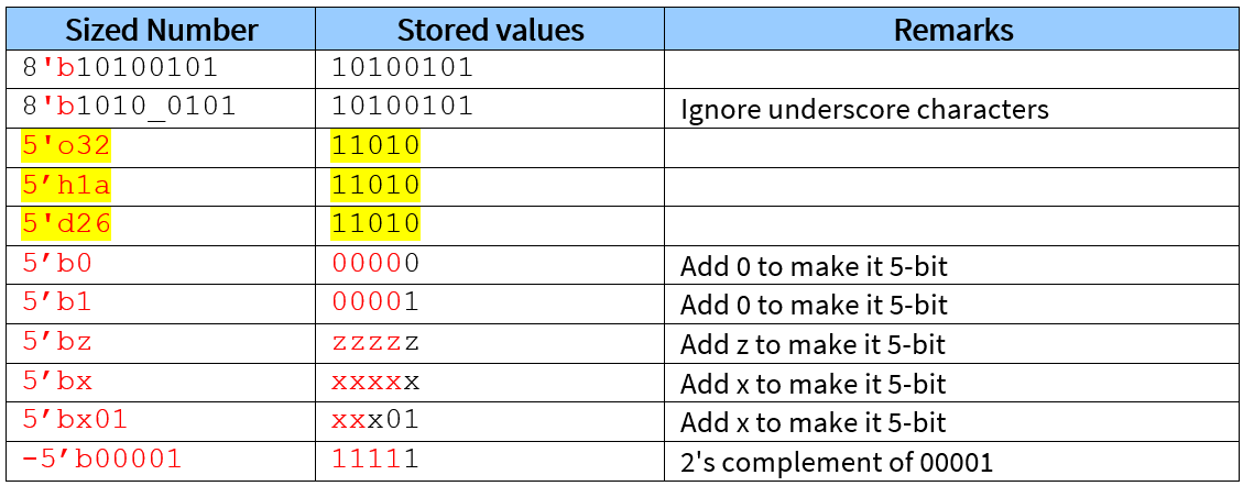
A. Sized Numbers
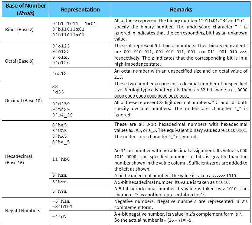
Specify the number or width of bits explicitly. Some examples of sized numbers can be seen in Table 1.
Important notes:
- If the number size is smaller (For example, only 1-bit) than the specified number size (For example, 5-bit), then the actual stored and compiled value will be added with 0s on the left, so that the number size becomes the same as the specified number size.
- However, if the leftmost bit is x or z, then the number x or z will be added to the left.
Table 1. Examples of sized numbers
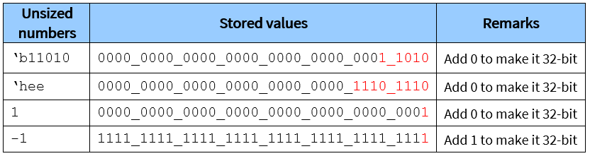
B. Unsized Numbers
Do not specify the number or bit width explicitly. Some examples of unsized numbers can be seen in Table 2.
Important notes:
- Unsized numbers omit the element of “size” in their representation.
- The actual number size depends on the data size/bit-width of the host computer architecture used in the digital system design, with a minimum size of 32-bit.
- In unsized numbers, the “radix/base” element can be omitted if the number is a decimal number (Base 10).
Table 2. Examples of unsized numbers
3. The [Radix] Element
The “Radix” element is a letter character that determines the base of a number.
- Numeric values that begin with the letter character “b” or “B” indicate that the number is a base 2 (Binary) number.
- Numeric values that begin with the letter character “o” or “O” indicate that the number is a base 8 number (Octal).
- Numeric values that begin with the letter character “d” or “D” indicate that the number is a base 10 number (Decimal).
- Numeric values that begin with the letter character “h” or “H” indicate that the number is a base 16 number (Hexadecimal).
The single quotation mark (‘) character in the radix element must be immediately followed by the character representing the base of the number (Radix). Whitespace between them is not allowed. However, whitespace can precede the size element of the number.
4. The [Value] Element
The “Value” element determines the value of a number in the appropriate base.
Important notes regarding the [Value] element:
- When writing value elements, an underscore character (“_”) can be added for clarity and readability. However, it will be ignored by the compiler (not synthesized by the compiler).
- In the Value element, capital letters can be used instead of lowercase letters. This means that in the case of writing a hexadecimal number value, the (Capital) letter character A, B, C, D, E, or F can be used instead of the (Lowercase) letter character a, b, c, d, e, or f to specify the corresponding hexadecimal digit. X or Z can be used instead of the value x or z, respectively.
6.5.1 Important Notes Regarding Number Representation
- Writing number representations must be written in series without spaces.
- The question mark character (“?”) can be used in place of the “z” value.
- If cutting or adding numbers on the left and/or right is often confusing, then it is better to represent the numbers in full.
6.5.2 Representation of Numbers/Integers
Examples of integer type number representations are presented in Table 3 below:
Table 3. Examples of integer number representations in Verilog programming
6.5.3 Real Number Representation
Real numbers can be expressed in decimal notation or scientific notation. Decimal notation has the form:
|
1 |
-a.b |
where a, b, the negative sign, and the decimal point have their usual meanings.
The numbers “a” and “b” must be present in the number. A number can be expressed in scientific notation as:
|
1 |
4.3e2 |
where 4.3 is the mantissa and 2 is the exponent (10 raised to the nth power). The decimal value of this number is 4.3 x 102 = 430.
Here is another example of numbers represented in scientific notation.
|
1 2 3 |
–7.3e2 –7.3e–2 7.3e–2 |
This representation is commonly used.
–7.3e2 = -7.3 x 10 to the power of 2 = -730
–7.3e–2 = -7.3 x 10 to the power of -2 = -0.073
7.3e–2 = 7.3 x 10 to the power of -2 = 0.073
6.6 Non-Recommended Number Representation Formats
The following is an example of a number representation that is not recommended for use in Verilog programming and its Testbench.
Below is an example of a valid number representation, but the size/bit-width is not explicitly defined:
|
1 2 3 4 5 6 |
3 28 255 –3 –28 –255 |
The following is an example of an invalid number representation because it represents a negative number with a non-decimal number (not allowed) and its size is not explicitly defined.
|
1 2 3 4 |
3a B7 –5a –B7 |
In Verilog programming, numbers that are not explicitly defined in size/bit-width are assumed to be 32-bits wide (by default). This results in the hardware area used by these numbers being the same, 32-bits, even though their values do not actually require a 32-bit size. This situation leads to inefficient use of hardware area (semiconductor wafers).
If a digital system design description has a number representation specified in the form given in the examples above, the Verilog code synthesis of the circuit will specify a 32-bit width for those numbers and for all associated circuits. Therefore, number representations such as those in the examples above, while simple, should be avoided in digital system design descriptions. Number representations in this format should also be restricted in testbench code generation.