Friends of Robonesia, in the world of digital electronics, the programming language used to design hardware for digital electronic systems is called a hardware description language, or HDL for short. In this article, and in syaa Allah, in future articles, we will invite you to learn one of the HDL programming languages: VHDL.
1.1 What is VHDL?
VHDL is a hardware description programming language (HDL), more commonly known as Hardware Description Language (HDL). VHDL describes the behavior of an electronic circuit or system. From this programming, the physical electronic circuit or system can then be implemented on a semiconductor wafer in the process of manufacturing integrated circuit (IC) chips.
VHDL stands for VHSIC Hardware Description Language. VHSIC itself stands for Very High-Speed Integrated Circuits, an initiative funded by the United States Department of Defense in the 1980s that led to the creation of the VHDL hardware programming language. The first version of VHDL was VHDL 87, which was later upgraded to VHDL 93 (released in 1993). VHDL is the original hardware description language and the first to be standardized by the Institute of Electrical and Electronics Engineers (IEEE), through the IEEE 1076 standard. This standard was ratified in 1987 and is therefore referred to as VHDL 87. An additional standard, IEEE 1164, was later added to introduce multi-valued logic systems.
VHDL is used for the synthesis and simulation of electronic system circuits. Although VHDL is fully simulative, not all electronic system circuit constructions created using VHDL can be synthesized. The fundamental motivation for using VHDL is that it is a standard, technology-independent, portable, and reusable HDL language.
VHDL is designed to be technology-independent. This means that if a design is described in VHDL and implemented in a current technology, the same VHDL description can be used as a starting point for a design in some future technology. Although originally conceived as a hardware documentation language, much of VHDL can now be used for logic simulation and synthesis
For prototyping and simulation purposes in the laboratory, the implementation of electronic circuit designs written using VHDL program code can be done on programmable semiconductor devices, such as CPLD (Complex Programmable Logic Device), FPGA (Field Programmable Gate Array), or ASIC (Application Special Integrated Circuits) or if for mass production and commercial purposes, then the VHDL code can be submitted to chip manufacturers (Foundries), such as TSMC, Samsung, Global foundry, and others to make IC products for commercial purposes (for sale). Currently, many complex commercial IC chips, for example, microcontrollers, microprocessors, graphic processing units (GPUs), or system on chips (SoCs) are designed using such an approach.
The main characteristic of VHDL is that statements in VHDL programming are processed inherently concurrently or in parallel, this is different from ordinary computer programming languages (e.g. C, C++, Java, etc.) whose statements are processed sequentially. Only statements placed within the PROCESS, FUNCTION, or PROCEDURE program blocks are executed sequentially. For this reason, VHDL is more accurately referred to as code, not a program.
VHDL can describe digital systems at several different levels: behavioural, data flow, and structural. For example, a binary adder can be described at the behavioural level by its function of adding two binary numbers without providing any implementation details. The same adder can be described at the data flow level by providing the logic equation for the adder. Finally, the same adder can also be described at the structural level by specifying the gates and interconnections between the gates that make up the adder.
VHDL naturally leads to a top-down design methodology, where the system is first defined at a high level and tested using a simulator. Once the system has been debugged at this level, the design can be gradually refined, ultimately leading to a structural description that closely matches the actual hardware implementation.
1.2 Digital System Design (VHDL) Flowchart
As mentioned above, one of the uses of VHDL is to synthesize a digital electronic circuit or system into a programmable device, such as a CPLD, FPGA, or ASIC. The general flow of steps for designing a digital electronic circuit or system using VHDL can be explained in Figure 1 below.
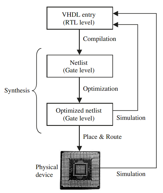
Figure 1. Flowchart for creating a digital system design (VHDL)
Source: Circuit Design With VHDL- Volnei A. Pedroni – Page 4
The first step in designing an electronic circuit is to write a VHDL program code which is stored in a file with the extension .vhd and the same file name as the ENTITY name in the program to make it easier to identify the name of the design project.
The second step is the VHDL program synthesis process, which involves two processes: compilation and optimization. Compilation is the conversion of the high-level VHDL language, which describes the circuit at the Register Transfer Level (RTL), into a netlist at the gate level (logic gate). Optimization, on the other hand, optimizes the netlist at the gate level for speed or area. At this stage, the electronic circuit design can be simulated.
The third or final step, the place-and-route (fitter) software will generate a physical layout for the CPLD, FPGA, or ASIC (Physical device) chip.
1.3 Electronics Design Automation (EDA) Tools
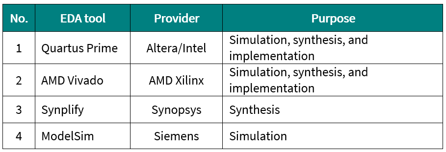
In the semiconductor industry, there are several EDA (Electronic Design Automation) software available for the purposes of simulating, synthesizing, and implementing electronic circuits using VHDL code, including the following:
Table 1. EDA tool references
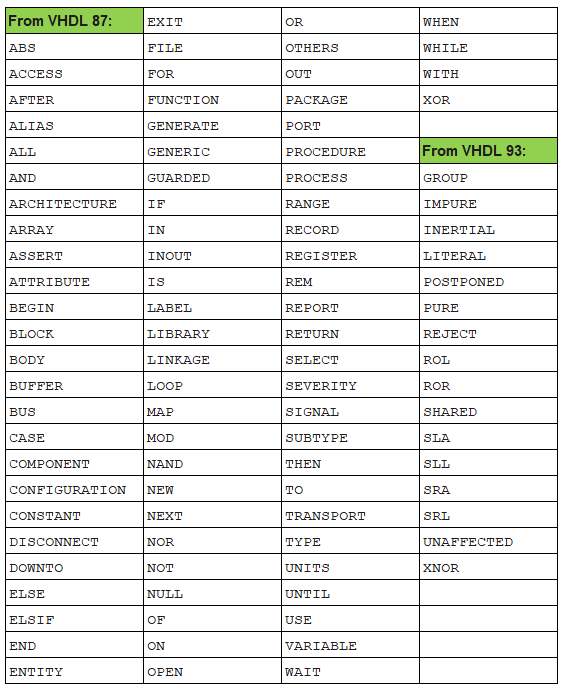
1.4 List of Keywords Used in VHDL
Like other programming languages, VHDL uses keywords. Electronic circuit designers using VHDL must be aware of the keywords used in VHDL so they don’t use them when creating VHDL program statements. The following table shows the keywords used in VHDL.
Table 2. VHDL keywords
Source: Circuit Design With VHDL- Volnei A. Pedroni – Page 367