Hello Robonesian, The VLSI (Very Large Scale Integration) industry comprises two major branches, system design and system verification. Hardware Description Languages (HDLs) such as Verilog and VHDL remain popular choices for most digital system designers. However, while initial functional verification can be performed using HDLs like VHDL and Verilog, both have limited capabilities regarding code coverage analysis and edge-case testing.
Consequently, specialized verification languages like SystemVerilog have emerged as the preferred choice for design verification. SystemVerilog supports Object-Oriented Programming (OOP). This enables features such as inheritance and polymorphism, thereby enhancing the ability to detect critical bugs within a design errors that might otherwise go undetected by standard HDLs like VHDL and Verilog.
Verification is arguably more complex and engaging than digital system design, and it utilizes a far greater number of OOP constructs compared to Verilog. SystemVerilog stands out as one of the most popular choices among verification engineers for digital system verification.
1. What is SystemVerilog?
SystemVerilog is a set of standard extensions to the IEEE 1364-2005 Verilog Standard (commonly referred to as “Verilog-2005”). The SystemVerilog extension for Verilog HDL described here is intended for designing and writing synthesizable models. This extension integrates many features from the SUPERLOG and C languages. SystemVerilog also contains many extensions for large design verification, integrating features from the SUPERLOG, VERA C, C++, and VHDL languages, along with OVA (OpenVERA Assertions) and PSL statements.
The integrated whole created by SystemVerilog far exceeds the sum of its individual components, creating a new type of engineering language, Hardware Description Verification Language or HDVL for short. Using one unified language allows engineers to model large, complex designs, and verify that they are functionally correct.
1.1 SystemVerilog Extensions for Verilog
By 2001, the size and complexity of digital ICs had grown significantly since the 1980s, when the VHDL and Verilog languages were first created. Even with the new features added in Verilog-2001, efficiently modeling these large designs and managing the vast amount of stimulus and response-checking code required to verify such complex designs was becoming increasingly difficult. To address the limitations of Verilog-2001, work began on defining a substantial set of new features for the Verilog language.
These extensions generated into two main categories:
- Enhancements primarily addressing the need to model digital logic functionality more efficiently and accurately.
- Enhancements on writing verification code efficiently for very large and complex designs.
Initial work to define this next generation of Verilog took place outside the IEEE, led by an independent non-profit organization called Accellera (now the Accellera Systems Initiative). Accellera is a think-tank organization comprising representatives from companies that develop Electronic Design Automation (EDA) software and companies that use such software. Accellera was formed in the mid-1990s through the merger of Verilog and VHDL user groups. Subsequently, other EDA groups, such as the SystemC Initiative, also joined Accellera. Accellera was responsible for the initial development of many EDA engineering standards used today. Many of these Accellera standards eventually became IEEE standards.
1.2 SystemVerilog Replaces Verilog
Shortly after releasing these two separate standards, the IEEE began merging them. In addition to the merger, the IEEE introduced a number of additional SystemVerilog features. The combined Verilog and SystemVerilog standard was released as IEEE SystemVerilog 1800-2009. At that time, the IEEE retired the older Verilog-1364 standard, and the name “Verilog” officially became “SystemVerilog.”
As the complexity of hardware designs and their verification continued to grow, the IEEE kept evolving the SystemVerilog standard to ensure its continued relevance. In 2012, the IEEE released the SystemVerilog 1800-2012 standard. Subsequently, in 2017, the IEEE developed SystemVerilog version 1800-2017. The SystemVerilog-2017 version provided clarifications to the standard but did not add any new language features to the 2012 version.
1.3 Why Is Verilog Disliked?
In the 1990s, Verilog was the primary language for verifying the functionality of integrated circuit (IC) designs that were small, relatively simple, and featured limited functionality. As IC design complexity grew, so did the need for superior tools for design and verification. SystemVerilog is far superior to Verilog due to capabilities such as constrained-random stimulus generation, the use of Object-Oriented Programming (OOP) features in testbench construction, functional coverage, assertions, and much more.
1.4 What is Verification?
Verification is the process of ensuring that a specific IC or semiconductor chip hardware design functions as intended. Chip design is an extensive and time-consuming process, with fabrication costs running into the millions. Detecting functional design flaws early in the process helps save costs; if a bug is discovered later in the design flow, the entire design process must be repeated, consuming significantly more resources, money, and time. Repeating the entire design flow in this manner is known as a chip re-spin.
2. SystemVerilog Modeling Abstraction Levels
SystemVerilog is capable of modeling digital logic at various levels of detail, referred to as “levels of abstraction.” Abstraction implies a lack of detail; the more abstract a digital model is, the less detail it contains regarding the hardware it represents. Figure 1 illustrates the primary levels of modeling abstraction available in SystemVerilog.
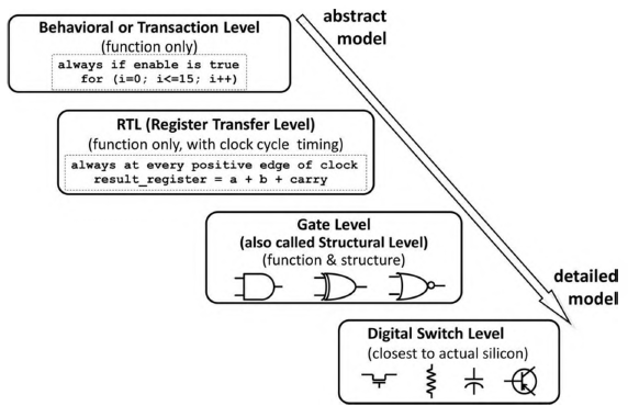
Figure 1. SystemVerilog modeling abstract level
Source: RTL Modeling with SystemVerilog for Simulation and Synthesis – Stuart Sutherland – Pages: 7
- Behavioral or transaction level. It is the most abstract of the digital system model. The abstract model containts with function only.
- Register Transfer Level (RTL). The abstract model containts with function only, but with clock cycle timing.
- Gate level or structural level. The abstract model containts with function and structure.
- Digital switch level. This is abstract model that closest to actual silicon (Hardware).
3. Electronics Design Automation (EDA) Tool for SystemVerilog
In the semiconductor industry, several EDA (Electronic Design Automation) software tools are available for the digital system design, simulation, verfication, synthesis, and implementation using SystemVerilog code, including the following:
3.1 Commercial EDA Tools for SystemVerilog
- Synopsys VCS: High-performance simulation and verification solution that natively supports SystemVerilog and Universal Verification Methodology (UVM).
- Siemens Questa: Comprehensive verification platform providing advanced SystemVerilog and UVM support, code coverage, and formal verification.
- Cadence Xcelium: Parallel functional verification platform designed for fast SystemVerilog simulation and UVM testbench performance.
- AMIQ EDA: Offers the DVT IDE for intelligent SystemVerilog code development, debugging, and the Verissimo linter.
3.2 Open-Source EDA Tools for SystemVerilog
- Verilator: Converts SystemVerilog/Verilog code into highly efficient C++ or SystemC code for fast cycle-based simulation.
- Icarus Verilog (iverilog): A lightweight, open-source Verilog and partial SystemVerilog simulation and synthesis tool.
- Yosys: An open-source framework for RTL synthesis that handles subsets of Verilog/SystemVerilog.
- Verible: A suite of SystemVerilog developer tools including a parser, linter, formatter, and structural analysis tools.
4. SystemVerilog Keywords
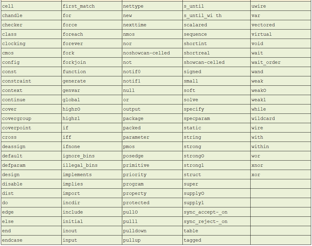
Like other programming languages, SystemVerilog uses keywords. Electronic circuit designers using SystemVerilog must be aware of the language’s reserved keywords to avoid using them when constructing SystemVerilog program statements. The following table lists the keywords used in SystemVerilog.
Table 1. SystemVerilog-2012 keywords list (1)
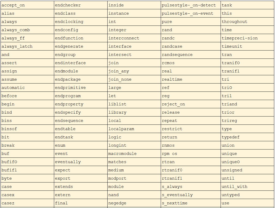
Table 2. SystemVerilog-2012 keywords list (2)