Hello Robonesians, after learning about Verilog programming in the previous article (Getting to Know Verilog Programming), in this article, we’ll continue our learning of Verilog programming, specifically exploring the structure of the Verilog programming language (Module Definition) and how to instantiate those modules.
The Verilog program structures presented in this article are based on four versions of the Verilog programming standard: the Verilog-1985/1995 standard and the Verilog-2001/2005 standard. Why are these four standards discussed? Because there are syntactic differences between the two groups of Verilog standards.
2.1 Verilog Program Structure (Standard Verilog-1985/1995)
Unlike the VHDL program structure, the general structure of a Verilog program is simpler. The main program is the definition of a program block called a “module.” Each program block begins with the keyword “module” and ends with the keyword “endmodule.” The following is the syntax of the main structure of Verilog program code, or the definition of a program module, following the Verilog-1985 and Verilog-1995 standards.
Syntax 1: Module Definition | Standard Verilog-1985/1995
|
1 2 3 4 5 6 7 8 9 10 |
module <module_name> (port1_name, port2_name,..., portN_name); input port2_name, ..., portN_name; output port1_name; module_item-1; module_item-2; ... module_item-n; endmodule |
In the syntax above, to create a digital circuit or system design program using Verilog programming, the first thing that must be determined is the module_name. Then followed by the signal name or I/O port name in the port/signal name list (port_list), without specifying the port/signal type (input, output, or inout). The I/O port/signal type must be declared in the module. After the I/O declaration, then continue with writing the program statements (module_item) needed to regulate the behavior or internal operation of the digital system design module being created. It is important to always remember that every statement in Verilog programming must end with a semicolon character (semicolon, “;”).
The program statement or module_item, can be:
- Data type declaration (Click here!).
- Parameter declaration (Click here!).
- Module instantiation (Click here!).
- Instantiating Pre-define primitives (Click here!).
- Instantiating User-define primitives (Click here!).
- Generate block (Click here!).
- Procedural block (Click here!).
- Continuous assignment (Click here!).
- Task definition (Click here!).
- Function definition (Click here!).
For example, consider program 1 and Figure 1-a. The module declaration is named two_gates. All input and output signals are listed in the signal/port list without specifying their type, whether input, output, or inout. The input and output port/signal declarations are placed inside the module. A, B, and D are input signals. E is an output signal. Signal C is declared inside the module as wire because it is an internal signal. The program continues with two concurrent statements describing where the two gates (NAND and OR) are located, and the module ends with the keyword endmodule.
Program 1:
|
1 2 3 4 5 6 7 8 9 |
module two_gates (A, B, D, E); output E; // Deklarasi port/sinyal output input A, B, D; // Deklarasi port/sinyal input wire C; // Deklarasi sinyal internal (wire) assign C = A && B; // concurrent statements-1 assign E = C || D; // concurrent statements-2 endmodule |
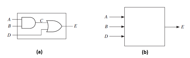
Figure 1. Illustration for a module in a Verilog program
Source: Digital Systems Design Using Verilog (Charles Roth, Lizy K. John, Byeong Kil Lee) – Pages 68-69
The module I/O declaration section can be thought of as a “black box” image of the designed module and its external interfaces, namely the I/O declarations (A, B, D, and E) that represent the module’s interconnection with the outside world. See Figure 1-b.
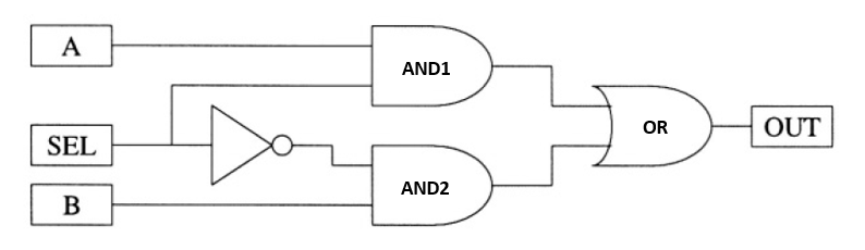
Figure 2. Digital multiplexer system design
Source: Verilog Quickstart, 3rd edition, James M Lee – Pages 14
By paying attention to the digital multiplexer system design in Figure 2, the following is an example of a complete program for the main program definition or module definition in Verilog programming by following the Verilog-1985/1995 standard.
Program 2: Verilog Gate-level program code – Module “mux”
|
1 2 3 4 5 6 7 8 9 |
module mux(OUT, A, B, SEL); output OUT; input A,B,SEL; not g_NOT (output_not, SEL) ; and g_AND1 (output_and1, A, SEL); and g_AND2 (output_and2, output_not, B); or g_OR (OUT, output_and1, output_and2); endmodule |
Program 2 explanation:
Line 1: module mux(OUT, A, B, SEL);
This line declares the module name and lists its input/output ports.
Line 2: output OUT;
This line tells the Verilog program code compiler the direction of the OUT port. “OUT” is the name of the port which is the output port. “output” is the Verilog program keyword used to declare the direction of the output port.
Line 3: input A, B, SEL;
This line tells the Verilog compiler the direction of ports A, B, and SEL, which are all input ports. “input” is a Verilog keyword used to declare the direction of an input port.
Line 5: not g_NOT (output_not, SEL);
This line instantiates the built-in primitive “not” (NOT gate). The first signal, output_not, is the output signal, and the second signal, SEL, is the input signal connected to the input of the NOT gate. “g_NOT” is the instantiation name of the built-in primitive “not”.
Line 6: and g_AND1 (output_and1, A, SEL);
This line instantiates the first AND gate (built-in primitive). This gate has the instantiation name g_AND1. A and SEL are the input signals of the first AND gate, while “output_and1” is the output signal of the first AND gate (AND1).
Line 7: and g_AND2 (output_and2, output_not, B);
This line instantiates the second AND gate (built-in AND gate). This gate has the instantiation name g_AND2. Output_not and B are the input signals of the second AND gate, while “output_and2” is the output signal of the second AND gate (AND2).
Line 9: or g_OR (OUT, output_and1, output_and2);
This line instantiates the built-in OR primitive (OR Gate). This gate has the instantiation name g_OR. Output_and1 and output_and2 are the input signals of the OR gate which are the output signals of AND1 and AND2 gates respectively, while “OUT” is the output signal of the OR gate which is also the output signal of the digital design of the multiplexer system.
Line 10: endmodule
This line marks the end of the MUX module which ends with the keyword “endmodule”.
2.1.1 Module Instantiation (Standard Verilog-1985/1995)
Module instantiation in Verilog programming is a way of using a previously defined module from within the main module of the digital system design being built.
The following are the steps for instantiating a module in Verilog programming following the Verilog-1985/1995 standard:
Step 1: Defining a Module
First, we must define the module we want to instantiate. Modules are defined within the module program block using the keyword “module,” followed by the module name and a list of input/output/inout ports associated with the module, and ending with the keyword “endmodule.” Program 3 is an example of defining a module.
Program 3: Module “adder”
|
1 2 3 4 5 6 |
// Module yang akan diinstansiasi dari module utama, “top” module adder(a, b, sum); input a, b; output sum; assign sum = a + b; endmodule |
Program 3 Explanation:
In the example above, we define a module named “adder” which has two inputs “a” and “b”, and one output “sum”. The function of this module is to add the inputs “a” and “b”, thus producing the output signal “sum”.
Step 2: Instantiating a Module
To instantiate a module, we create the main module of the digital system design we are building. Then, to instantiate another module that has been defined previously (in Program 3), write one line of program code in the main module whose elements are written sequentially, namely module_name, instance_name, and list_ports associated with the instance. Please see syntax 2.
Syntax 2:
|
1 |
module_name instance_name(.port_name1(signal), .port_name2(signal), ... ); |
Program 4 is an example of a main module that instantiates the “adder” module in program 3.
Program 4: Module “top”
|
1 2 3 4 5 |
// Module yang menginstansiasi module “adder” module top; wire [3:0] r, s, jumlah; adder u_adder (.a(r), .b(s), .sum(jumlah)); endmodule |
Program 4 Explanation:
In the example above, we instantiate the “adder” module from within the “top” module with the instance name “u_adder”. Then we connect the “a”, “b”, and “sum” ports of the “adder” module to the “r”, “s”, and “sum” signals defined in the “top” module.
Writing a Complete Verilog Program
Here is Program 5, a complete Verilog program that shows the definition of the “adder” module and its instantiation in the “top” module:
Program 5:
|
1 2 3 4 5 6 7 8 9 10 11 12 13 14 15 16 17 18 19 |
// Definisi modul top (Module utama) module top; wire [3:0] r, s, jumlah; reg [3:0] result; adder u_adder (.a(r), .b(s), .sum(jumlah)); //Instance modul adder assign result = jumlah; initial begin r = 4'd2; s = 4'd3; #10 $display("hasil = %d", result); end endmodule // Definisi modul adder yang diinstansiasi module adder(a, b, sum); input [3:0] a, b; output [3:0] sum; assign sum = a + b; endmodule |
Program 5 Explanation:
In the above example, we define the “adder” module and instantiate it in the “top” module. We connect the “a”, “b”, and “sum” ports of the “adder” module with the “r”, “s”, and “jumlah” signals defined in the “top” module. We also connect the “jumlah” output of the “u_adder” instance with the “result” signal in the “top” module. Finally, we display the result of the sum of “r” and “s” using string function “$display.”
2.2 Verilog Program Structure (Standard Verilog-2001/2005)
The main structure of Verilog program code, or module definition, in the Verilog-2001/2005 standard remains the same, beginning with the keyword “module” and ending with the keyword “endmodule,” but there are slight differences, namely differences in I/O port declarations and the addition of parameter declarations (optional). Here is a complete explanation.
1. Differences in I/O port declarations
In the Verilog-2001/2005 standard, in a module definition, the port_list (port-list) is written as an I/O port declaration and is immediately written complete with the signal direction, namely input, output, or inout. The port-list is written in ANSI-C style or C programming language style. After writing the I/O port declaration, the program code continues by writing the required module_item. Note the following Syntax 3:
Syntax 3: Module definition – Standard Verilog-2001/2005.
|
1 2 3 4 5 6 7 8 9 |
module <module_name> (deklarasi_port_output port1_name, port2_name, ..., deklarasi_port_input port1_name, port2_name, ...); module_item-1; module_item-2; ... module_item-n; endmodule |
Example 1:
|
1 2 3 4 5 6 7 8 9 10 |
// Modul adder yang menjumlahkan dua nilai 4-bit module adder ( input [3:0] a, // Input 4-bit input [3:0] b, // Input 4-bit output [3:0] sum // Output 4-bit ); // Fungsi untuk menjumlahkan input a dan b assign sum = a + b; endmodule |
Example 1 Explanation:
In the example above, we define an adder module that has three ports, namely Port a is a 4-bit input, Port b is a 4-bit input, and Port sum is a 4-bit output. The function of this module is to add the input signals a and b and produce a sum output signal.
2. Adding parameter declarations (Optional)
When defining a Verilog program code module following the Verilog-2001/2005 standard, we can add parameter declarations, but this is optional. Parameter declarations are written in parentheses, preceded by the hashtag “#.” This is followed by the I/O port declaration (input, output, or inout), and the required program statement or module_item. Note the following Syntax 4:
Syntax 4: Module definition follows the Verilog-2001/2005 standard with parameter declarations.
|
1 2 3 4 5 6 7 8 9 10 |
module <module_name> #(deklarasi_parameter1, deklarasi_parameter2,...) (deklarasi_port_output port1_name, port2_name, ..., deklarasi_port_input port1_name, port2_name, ...); module_item-1; module_item-2; ... module_item-n; endmodule |
Example 2:
|
1 2 3 4 5 6 7 8 9 10 11 |
module adder #( parameter BIT_WIDTH = 4 ) ( input [BIT_WIDTH-1:0] a, // Lebar bit = [4-1:0] = 4 bit input [BIT_WIDTH-1:0] b, output [BIT_WIDTH-1:0] sum ); assign sum = a + b; endmodule |
Example 2 Explanation:
Note that we use the BIT_WIDTH parameter declaration to specify the bit width of the input and output. Thus, we can easily change the bit width of the adder module without having to change the program code.
By declaring parameters, we can create more flexible modules that can be used in a variety of situations. Furthermore, we can provide default values for parameters, so that if we don’t specify a parameter value when instantiating the module, the default value will be used.
2.2.1 Module Instantiation (Standard Verilog-2001/2005)
Module instantiation in Verilog programming following the Verilog-2001/2005 standard can be done without adding parameter declarations or with adding parameter declarations. A complete explanation is provided below.
A. Module Instantiation Without Parameter Declaration
Module instantiation without parameter declarations can be done based on port connections, namely port order connections and port name connections. For syntax, please see Syntax 5 and Syntax 6.
Syntax 5: Port order connection
|
1 |
module_name instance_name instance_array_range (signal, signal, ...); |
Syntax 6: Port name connection
|
1 2 |
module_name instance_name instance_array_range ( .port_name(signal), .port_name(signal), ... ); |
Explanation of syntax 5 and 6:
- Port order connection : Lists signals in the same order as the ports are listed in the module definition. Unconnected ports are indicated by two commas with no signals listed.
- Port name connection : lists the port names and signals connected to them, in any order.
- instance_name : Specifying an instance_name is mandatory. This is used to create multiple instances of the same module that are unique from each other.
- instance_array_range : Specifying instance_array_range is optional. Used to instantiate multiple modules, each instance corresponding to a different bit of a vector.
-
- The array range is defined as [left_hand_index : right_hand_index].
- If the bit width of a module port in the array is the same as the width of the signal connected to it, the full signal will be connected to each module instance.
- If the bit width of a module port differs from the width of the signal connected to that port, each module port instance is connected to a selected portion of the signal, with the index of the rightmost instance connected to the rightmost portion of the vector, and continuing leftward.
- There must be the right number of bits in each signal to connect to all instances (the signal size and port size must be multiples).
- Instance arrays were added in Verilog-1995, but many software tools did not support them until Verilog-2001.
- Multiple module instances can also be created using the generate block (see the article titled “Generate Blocks in Verilog Programming”).
Program 6: Example of module instantiation without parameter declaration
|
1 2 3 4 5 6 7 8 9 10 11 12 13 14 15 16 17 18 19 20 21 22 |
module reg4 (output wire [3:0] q, // Module utama (yang meng-instansiasi) input wire [3:0] d, input wire clk); // Intansiasi port order connection, Port-2 tidak dihubungkan dff u1 (q[0], , d[0], clk); // Intansiasi port name connection, Port “qb” tidak dihubungkan dff u2 (.clk(clk), ,.q(q[1]),.data(d[1])); endmodule // ------------------------------------------------------- module dff (output q, // Module yang di instansiasi output qb, input data, input clk); dff_udp #(1) (q, data, clk); not (qb, q); endmodule |
Program 6 Explanation:
The “Reg4” module
is the main module that instantiates the “dff” module twice. This module has three ports:
- Port “q” : 4-bit input representing the register value.
- Port “d” : 4-bit input that represents the data to be stored in the register.
- Port “clk” : Clock output that represents the clock signal to update the register value
In the “reg4” module, there are two instances of the “dff” module, namely:
- Instantiation of “u1”: The first instantiation uses the port order connection method, which specifies the port names according to the order of port declarations in the “dff” module. However, port “qb” is not connected.
- Instantiation of “u2”: The second instantiation uses the port name connection method, namely by explicitly mentioning the port name using the syntax “.port_name(port_name)”.
The “DFF” module
is a module instantiated by the “reg4” module. This module has four ports, namely:
- Port “q” : Output that represents the register value.
- Port “qb” : Output that represents the inverse value of “q”.
- Port “Data” : Input that represents data to be stored in the register.
- Port “clk” : Clock input that represents the clock signal to update the register value
In the “dff” module, there are two statements:
- dff_udp #(delay) (q, data, clk); : This statement instantiates the “dff_udp” module with a “delay” of 1ns to set the delay for updating the register values and connecting the “q”, “data”, and “clk” ports to the “dff_udp” module.
- not (qb, q); : This statement instantiates a NOT logic gate that produces the inverse value of “q” and connects its output to port “qb”.
B. Module Instantiation with Parameter Declaration
Parameter values in a module can be redefined for each module instantiation. Only parameter declarations can be redefined, while “localparam” and “specparam” constants cannot be redefined.
Based on the method of redefining parameter values, module instantiations that use parameters following the Verilog-2001/2005 standard have three syntactic models, namely:
1. Explicit redefinition using the “defparam” statement with the parameter’s hierarchical name.
Syntax 7: Explicit Parameter Redefinition
|
1 |
defparam instance_name.parameter_name = value; |
2. Implicit redefinition uses the hashtag “#” as part of the module instantiation. Parameter values are redefined in the same order as they were declared within the module.
Syntax 8: Implicit Parameter Redefinition
|
1 |
module_name #(value,value, ...) instance_name (signal, ... ); |
3. Explicit redefinition uses the hashtag “#” as part of the module instantiation. Parameter values can be redefined in any order. Explicit parameter redefinition was added to the Verilog-2001 standard.
Syntax 9: Explicit Parameter Redefinition (added in Verilog-2001)
|
1 2 |
module_name #(.parameter_name(value), .parameter_name(value), ...) instance_name (signal, ... ); |
The following is an example of module instantiation with parameter declaration (Program 7).
Program 7: Example of module instantiation with parameter declaration
|
1 2 3 4 5 6 7 8 9 10 11 12 13 14 15 16 17 18 19 20 21 22 23 24 25 26 27 28 29 |
// Module utama yang meng-instansiasi module main (output wire [3:0] q, input wire [3:0] d, input wire clk); // Explicit parameter redefinition dff u3 (q[2], ,d[2], clk); defparam u3.delay = 3.2; // Implicit parameter redefinition dff #(2) u4 (q[3], , d[3], clk); // Explicit parameter redefinition dff #(.delay(3)) u5 (q[3], , d[3], clk); endmodule // ------------------------------------------------------- // Module yang diinstansiasi module dff (output q, output qb, input data, input clk); parameter delay = 1; // Nilai default parameter “delay” dff_udp #(delay) (q, data, clk); not (qb, q); endmodule |
Program 7 Explanation:
– Main Module:
The “main” module is the primary module that instantiates the “dff” module three times. This module has three ports:
- Port “q” : 4-bit output representing the register value.
- Port “d” : 4-bit input that represents the data to be stored in the register.
- Port “clk” : Clock input that represents the clock signal to update the register value.
In the “main” module, there are three instances of the “dff” module in different ways:
- Instantiation of “u3” : The first instantiation uses the port order connection method, specifying the port names according to the order of port declarations in the “dff” module. However, port “qb” is not connected. Additionally, the “delay” parameter in the “dff” module is changed to 3.2 using the “defparam” statement.
- Instantiation of “u4” : the second instantiation using the port order connection method, but the port “qb” is not connected and the implicit parameter redefinition method, namely the “delay” parameter in the “dff” module, is changed to 2 using the syntax “#(2)”.
- Instantiation of “u5” : the third instantiation using the port order connection method, but the port “qb” is not connected and the explicit parameter redefinition method, namely the “delay” parameter in the “dff” module is changed to 3 using the syntax “#(.delay(3))”.
– Using Defparam
The “ defparam ” statement is used to change the value of a parameter in an instantiated module. In this example, “defparam” is used to redefine the value of the “delay” parameter in the “dff” module u3 to 3.2.
– Use of Implicit and Explicit Parameter Redefinition
- Implicit parameter redefinition is a way to change the value of a parameter in an instantiated module without explicitly naming it. In this example, the syntax “#(2)” is used to change the value of the “delay” parameter in the “dff” module u4 to 2.
- Explicit parameter redefinition is a way to change the value of a parameter in an instantiated module by explicitly specifying the parameter name. In this example, the syntax “#(.delay(3))” is used to change the value of the “delay” parameter in the “dff” module u5 to 3.
– DFF Module:
The “dff” module is a module instantiated by the “main” module. This module has four ports, namely:
- Port “q” : Output that represents the register value.
- Port “qb” : Output that represents the inverse value of “q”.
- Port “Data” : Input that represents the data to be stored in the register.
- Port “clk” : Clock input that represents the clock signal to update the register value.
The “dff” module also has a “delay” parameter whose default value is 1. This parameter is used to set the delay time for updating the register value.
In the “dff” module, there are two statements:
- dff_udp #(delay) (q, data, clk); : This statement instantiates the “dff_udp” module with the “delay” parameter and connects the “q”, “data”, and “clk” ports to the “dff_udp” module.
- not (qb, q); : This statement instantiates a NOT logic gate that produces the inverse value of the output signal of port “q” and connects its output to port “qb”.